LNA specifications and measurements
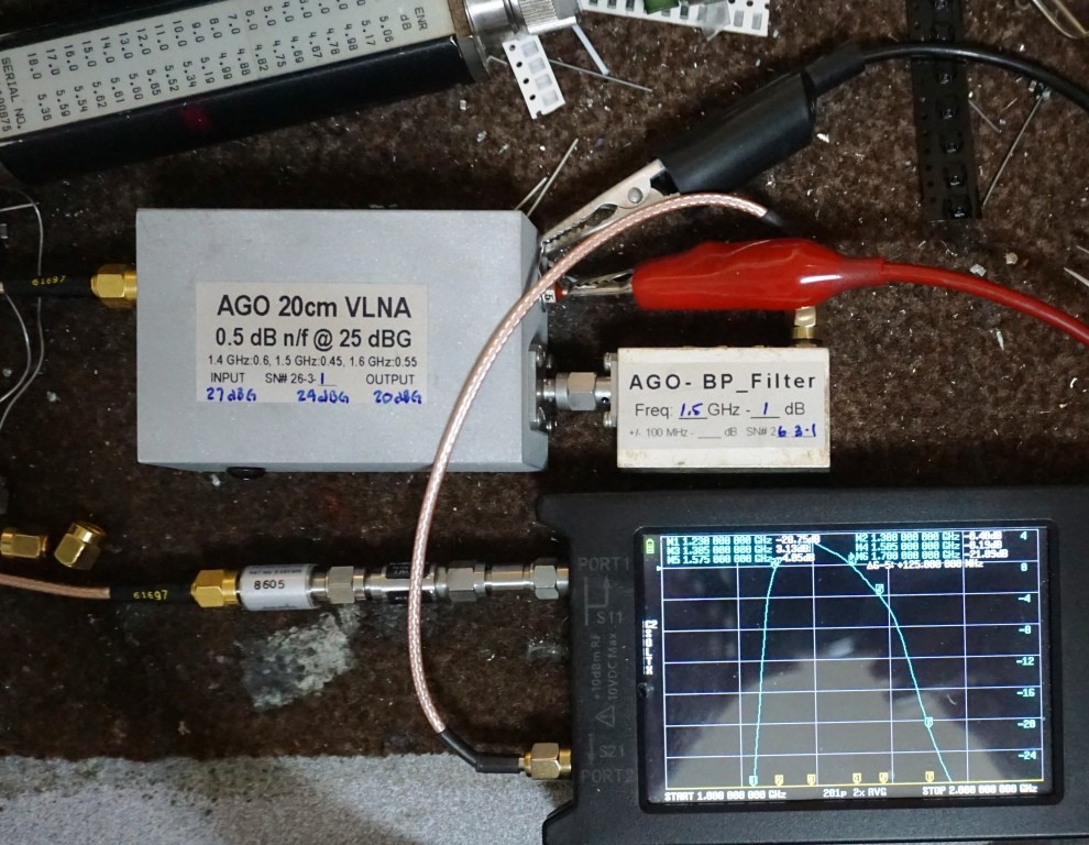
AGO 20cm VLNA — custom cavity low-noise amplifiers with bandpass filters, procured April 2026.
The SALSA antennas operate in an increasingly challenging RFI environment, with strong interference found below 1 GHz and above 1.7 GHz (worst peaks around 1800 and 2150 MHz). This was overloading the previous wide-band RAS LNA (1–2 GHz), causing intermittently very noisy spectra. The solution was to replace the LNA with a unit that filters out-of-band signals before amplification.
Four custom AGO 20cm VLNA units with integrated bandpass filters were built by Tommy Henderson (WD5AGO). The design addresses a key challenge: a standard 50-ohm bandpass filter placed before an LNA adds 0.6–1 dB of loss, degrading the noise figure. These units solve this by using an input cavity filter matched directly to the transistor, keeping the noise figure below 0.5 dB despite the input filtering.
Each unit's internal signal path is: input cavity filter → higher-IP transistor stages (up to +16 dBm output IP) → internal 2nd-stage filter and amplifiers → external WB cavity output filter. The high output IP makes the LNA resistant to overload from strong out-of-band signals. The aluminium cavities are machined to approximately 20 cm.
The LNA itself (95 × 50 × 27 mm including SMA connectors) has SMA female input and output connectors. The external output filter (57 × 34 × 20 mm including SMA connectors) has SMA-M input and SMA-F output and connects directly to the LNA output. Power is supplied via a Bias-T placed after the output filter — the cavity filters do not pass DC, so the Bias-T cannot be placed on the antenna side.
Specifications
Recommended operating range: 1350–1600 MHz
Power supply: 11–20 VDC, ~145 mA (±10 mA)
Connectors: SMA female input and output (LNA); SMA-M/SMA-F (external filter)
| Frequency | Gain | Noise figure | Notes |
|---|---|---|---|
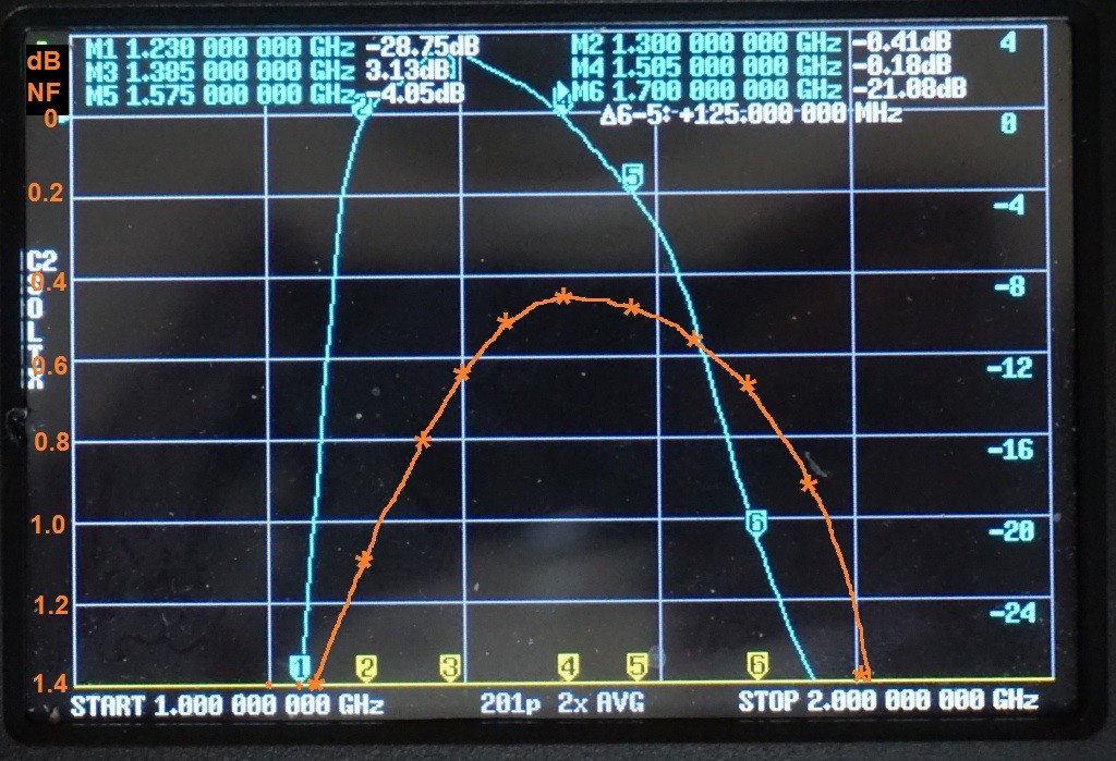
| 1230 MHz | −2.75 dB | — | Filter 3-dB point |
| 1385 MHz | 29 dB | — | Gain peak |
| 1420 MHz | 27.5 dB | 0.58 dB | HI line |
| 1500 MHz | 26 dB | 0.45 dB | Noise figure minimum |
| 1575 MHz | 22 dB | 0.49 dB | GPS L1 |
| 1700 MHz | ~5 dB | <1 dB | Filter roll-off |
| 1750 MHz | −2.75 dB | — | Filter 3-dB point |
| >2000 MHz | <−40 dB | — | Out-of-band rejection |
Unit variation
Three of the four units measure approximately 27 ±1 dB gain at 1420 MHz. The fourth unit has 25 dB gain at 1420 MHz — it was intentionally tuned with a wider bandwidth toward 1575 MHz, giving a flatter response across the band. All four units are better than −40 dB above 2 GHz.
Measurements
The VNA sweep shows gain (blue) and noise figure (orange) from 1–2 GHz. A 26 dB attenuator was used in the gain measurement path — add 26 dB to the displayed gain values to get the actual gain.